 In the first part of this article I introduced the concept for the WorldTV set-top box and some basic requirements.
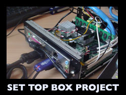
In this part I delve deeper into the hardware-side and show just how easy it is to make your own streaming set-top box (aka TV PC, aka Over the top Set Top Box).
Traditional set-top boxes are dedicated hardware devices. They are custom made to a precise specification and have custom software that makes them proprietary and ‘closed’. This has the advantage of making them reliable, quick to start up, and cost efficient. There is no wasted hardware.
The downside is that they are inflexible, take a long time to bring to market, and are inevitably based on old technology. Designing a user interface for them is a huge pain – just ask anyone who’s had to design a user interface for cable TV. A user interface designed for one set-top box typically doesn’t work on another – it’s a nightmare.
The WorldTV set-top box prototype will be different. It will use a computer based architecture with an operating system and browser to load the UI. The challenge will be to make it start up quickly and be reliable. People are used to TV equipment being extremely reliable – TV’s don’t crash.
In its simplest terms I’ll be building a small computer and putting software on it. The software will take the longest to perfect and will be an evolutionary process. The hardware side will be the easy bit and I cover that today.
If you’ve built your own PC before, you know how easy it actually is. If you haven’t, this guide may just be the catalyst for you to try it yourself. I certainly hope so. To that end I’ll be writing easy to follow instructions.
The Parts you will Need
A standard component list for a PC typically looks like this…
- Motherboard
- Processor
- Hard drive
- Memory
- A DVD drive
- A case with built-in power supply
Each of these components can be readily bought at low cost from a myriad of sources, even from local no name computer stores. All of them come in standard sizes and fittings and use standard connections. They come with the screws and connectors you need.
A PC set-top box is no different, it’s just smaller than a typical PC. Small PC components are a specialist item but they can be readily bought from a cottage industry of suppliers. Good suppliers I’ve found (I’ve not tried all of them) include Mini-ITX.com, Cappuccino PC and ITX Warehouse in the UK.
The parts list I settled on…
- An amazing low cost motherboard from Intel featuring built in Atom processor
- 7200rpm laptop drive (for now) – Solid State Drive later
- 2GB RAM stick
- Miniature ‘PicoPSU‘ 90W power supply
- Mini-ITX M350 case
- USB wi-fi adapter – to provide wireless internet access
The parts have arrived and here they are…
Motherboard
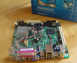 I chose the Intel Little Falls 2 Motherboard (D945GCLF2) as the basis for the system. It cost £65 ($89).
The advantages of this motherboard are that it comes with a very capable processor included, it has s-video/composite video output for a TV and is incredibly cheap. A 1.6ghz dual-core Atom 330 is the processor and is the more capable cousin of the same chip used in many net-book PCs. I know from experience a net-book is capable of displaying medium-definition flash video, so my highly scientific calculation is is that this chip will be fast enough for the set-top box.
UPDATE: This was written in July 2009. There are now better motherboard options available with HDMI output in the ‘Mini-ITX’ size. There are also mini PC’s like the Raspberry Pi etc that have HDMI output and can run 1080p video.
The Case
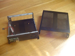 The case for any ‘production’ version of a set-top box would almost certainly be custom made. For the prototype, I’ve chosen a versatile off-the-shelf case designed for mini-ITX motherboards like the Little Falls 2.
Even by mini-ITX standards the M350 is a diminutive case as it does away with a DVD drive. What I most like is the hidden area at the front of the case for enclosing a USB stick. This is perfect for the wi-fi adapter I plan to use. This hidden area is unshielded – meaning the wireless signals will pass through. The case is also covered in ventilation holes so will run cool. The case was not cheap at £45 ($39 in the US!). It would be much cheaper with a custom designed version.
Hard drive and Memory
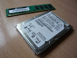 To keep the cost down I originally considered using a USB stick as the hard drive. I may revisit this idea, but for now it’s all about speed, and that means something more traditional. An ultra high speed, solid state disk like those from OCZ would be the performance option and these will come down in price over the next couple of years. I will try one of these later, but for now I am using a recently retired 7200rpm laptop drive.
Memory – The Little Falls 2 uses standard PC memory modules and has a max capacity of 2GB. I chose a Corsair 2GB stick that cost £15 ($22). The full spec is 533 mhz DDR2 Non ECC, CL4, unbuffered 240pin DIMM SDRAM. You can also use 667 or 800 mhz modules and they will simply run at the lower 533 mhz speed. Sometimes faster memory is cheaper. For me, 667 mhz memory was cheaper than 533, so I used that.
The power supply
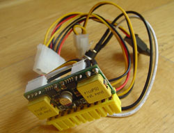 Any PC motherboard has a silly amount of power needs – all different voltages and currents. The power connector on a motherboard typically has 20 pins or more. I chose the Pico PSU which is a tiny board that takes a single 12v input and generates those 20 different connections. This greatly simplifies matters. I will use an external AC adapter to provide the 12v power. You could also run it off a car.
The Pico PSU cost £21 ($30).
Total cost so far: £145 ($200)
This is twice my target ‘production’ budget, but for a prototype this is in the ballpark.
Putting it all together
Step 1 – Installing the motherboard
 The first step is to mount the motherboard in the case. Mini-ITX motherboards use 4 small screws in standard positions (supplied) and a metal backplate (supplied) that pops into a rectangular hole in the back of the case.
Shimmying the motherboard and backplate into the case was a little fiddly, the case is barely bigger than the motherboard, but it was ultimately not difficult. I got the motherboard in first and then slid in the backplate from the side.
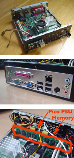
Step 2 – Adding the PSU and memory
The Pico power supply slides onto the 20 pin connector on the motherboard. Actually the motherboard has a 24 pin connector but the two are compatible. You connect it the only way that it will go.
A second connector from the Pico PSU attaches to a separate point on the motherboard (see the manual for directions) and there is a third connector for powering a hard drive. The PicoPSU comes with a standard 12v DC in jack, complete with ring nut, and this fits in a convenient hole on the back of the case.
Slotting in the memory is simplicity itself. It can only go one way and you just have to remember to ground yourself first, and pop out the white plastic clips before pushing the memory in. The clips lock back into place as you push the RAM in. For grounding I just touch a metal object connected to the ground such as a radiator or computer case.
Step 3 – Connect the power switch, power indicator and front USB connecters
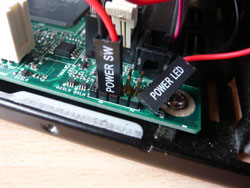 Your set top box case may differ but mine required hooking up a connector for the front power switch, the front power indicator and the front USB port. The motherboard manual shows where to hook these up. If it’s your first time building a PC, be aware these slide onto pins on the motherboard. Some are polarized meaning they are a pair which must be connected the right way round. Refer to the motherboard manual and remember red means positive, black (or white) means negative.
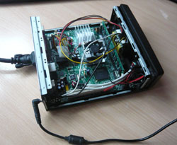
Step 4 – Connecting a monitor, the AC adapter and the first boot
 The last three steps can be done in under 30 minutes and already its time for the first boot. You don’t need a hard drive for this as the goal is to simply get as far as the BIOS screen, which is a screen for changing motherboard settings.
Before you do this you will need to connect a monitor using a VGA cable. This is the older style of cable and most monitors still have this style of connection. It is unlikely you will have success booting into BIOS from the S-Video connection – it’s not worth trying actually. Your motherboard, if different, may have a DVI connector instead.
Before powering up you will want to move a small jumper switch on the motherboard that changes it from ‘normal’ mode to ‘configuration’ mode. See the manual for this. This makes the motherboard boot into BIOS without needing to connect a keyboard. Usually you boot into BIOS by holding down the F2 key on a keyboard at startup.
The final step is to connect the AC adapter. You will need an AC adapter that is rated 12V and 5A or higher. If the adapter is rated in watts the equivalent is 60 watts (or higher). I used a multi-voltage adapter from an electronics shop which I set to 12v and 5A.
Hopefully your first boot will go a little better than mine. In my excitement over finding a large AC adapter lying around that was 12v and had the right connector, I failed to notice it was only rated at 1A (the equivalent of 12 watts) and this was not enough. While the Intel Little Falls 2 motherboard has an ultra low power processor (an amazing 4 watts), the graphics hardware is old and inefficient. It adds over 20 watts for a total power need of 35-40 watts. Add in a hard drive and a wireless stick and you get to 60 watts.
The least you need to know is that you will need an AC adapter rated at 5A or more for this motherboard.
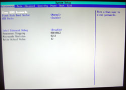
A last check of all the connections and it’s time to press the power switch. All being well you will be greeted by the BIOS screen (pictured) and will be well on your way to building your own set-top box.
Read Pt 3: Installing the hard drive and operating system, getting online
I think this is just the beginning. This is just the tip of the iceberg of things to come for most customers in India when it comes to DTH. I think Tata Sky forward following this method to attract more, and nobody knows they might even waive off monthly expenses too soon!
Thanks for the write up. Just as i was imagining the thought of building a set top box and wondering if it will work, i came across your write up. It is brilliant.
Have you figured out how to improve on the UI for example with a remote control? What about using a moile usb modem? Can you figure out how this can be made to connect automatically at boot up or boot up the service privider page when the user can be prompted to click on a button to connect. There may be proprietory boxes out there with these features already- any idea?
very helpful thanks but your link is dead
Thanks for bringing this to my attention. I’ve fixed the links now. Cheers.